
Condition monitoring engineers are typically taught to perform single plane balance with a full vector plot. In practice calculators are usually used for convenience. This software bridges the gap allowing a full plot to be drawn on the IPAD without the need for graph paper and protractor.
Drag the positions of the Initial Run, Trail Mass and Trail Run will cause the correction mass move into the correct position for trim balance. Drawing blades automatically produces split weights. The direction of rotation, phase (leading lagging) can all be adjusted.
NOTES
Units entered will be the output units with regard to vibration and mass units (i.e if the Trial Weight is in Grams the output displayed on the chart will be in Grams also). All weights (trial and correction) must be placed at the same radius. Select an appropriate measurement unit based on the available transducers, the bearing type and machine speed.
If applicable enter the number of blades or bolt positions where correction weights can be fitted in the box marked (# Blades) and hit the DRAW button next to it
PROCEDURE
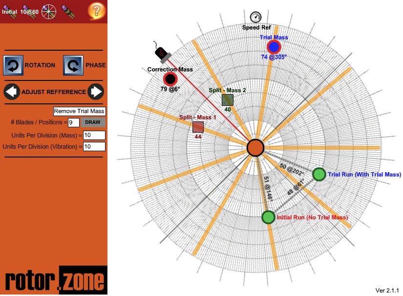
Select an appropriate transducer placement, preferably a radial position at a bearing adjacent to the balance plane. When using seismic transducers the vertical and horizontal vibration should be measured at the selected plane. The direction which exhibits the maximum 1 x rpm response should be used as the reference direction. In the example shown the position of the transducer has been shown by the red line on the graph. This marker (0° Ref) can be adjusted using the “ADJUST REFERENCE” buttons
Run the machine and measure the amplitude and phase of the 1 x rpm response. Now drag the green dot marked “Initial Run” into position. In this example above the result of the initial run was at 51mm/s @ 146°.
Note – it is very important that consistent conditions are attained in each occasion before the balance vectors are measured. Factors that must be maintained constant are speed, load and machine temperature. Only when the machine has reached stable conditions should the balance vectors be measured.
Now drag the blue dot marked “Trial Mass” into position. In this example a mass of 74 grams at 305° has been used.
Care should be taken to do a reality check on the weight calculated based on a common sense analysis of the situation and any previous balance history available for the machine.
As mentioned previously the trial weight should be placed in a position that will reduce the overall level of vibration, however regardless of where the weight is placed this will be used as the reference (usually identified as 0°) on the rotor for all further balance weight attachment. As mentioned previously the data analyser used in this example uses the phase lag convention and the direction of shaft rotation is clockwise, hence a vector diagram should be created which is consistent with the diagram shown above (i.e rotation clockwise and phase in the opposite direction).
Now drag the green dot marked “Trial Run” into position. In this example above the result of the initial run was an 50mm/s @ 202°.
The position of the “Correction Mass” will be shown on the vector diagram (Black Dot). In this example the correction mass is 79 @ 6°.
If blades have been drawn then the weight automatically split. Split - Mass 1 (Red) is shown as 44 grams and Split - Mass 2 (Green) is shown as 40 grams.
Note that in the example above the trial mass has been removed from the machine before calculating the correction mass. Clicking on the button marked “Remove Trial Mass” will toggle between leaving the trail mass in place and removing it.