
INSTRUCTIONS
NOTE - Units entered will be the output units with regard to vibration and mass units (i.e if the Trial Weight is in Grams the output displayed on the chart will be in Grams also). All weights (trial and correction) must be placed at the same radius.
1. If applicable enter the number of blades or bolt positions where correction weights can be fitted in the box marked (# Blades) and hit the DRAW button next to it - See Screen Shot. When this option is used the GREEN and BLUE circles will auto centre on the positions closest to 240º and 120º respectively.
2. Run machine, measure vibration and record amplitude in the Run 1 (BLACK) position.
3. Stop machine and place trial weight at initial arbitrary position on chosen balance plane. Mark position of the initial balance weight as this will be used as the reference position for future attachments and the final solution. Enter the trail weight in the trail weight box (see screenshot)
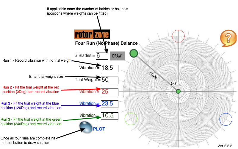
4. Restart machine and record vibration amplitude as Run 2 (RED Position) - See Screenshot above
5. Stop machine and move trial weight by 120 degrees clockwise to the Run 3 (BLUE Position). Care should be taken to maintain the same radius and plane as the first trial weight. The position of blades or other areas for weight attachment may make 120 degrees impossible to achieve. In this instance use the closest available position and measure/calculate the angle used. Mark position of trial weight so that this can be identified as the second trial weight position.
6. Restart the machine and record vibration amplitude in the Run 3 (BLUE position). - See Screenshot above
7. Stop machine and move trial weight clockwise to a position 240 degrees from the initial reference position to the Run 4 (GREEN position). Care should be taken to maintain the same radius and plane as the first trial weight. Mark position of trial weight so that this can be identified as the third trial weight position. Again note the angle if it is not 240 degrees.
8. Restart machine and record vibration amplitude in the Run 4 (GREEN Position). - See Screenshot above
9. To derive the graphical solution hit the “PLOT” button
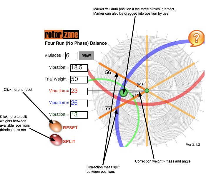
10. When circles have been plotted for the three trial runs they should intersect (or nearly intersect) at one point. This point is the end of the balance correction vector. The correction mass must be placed at the same radius and plane as the trial weights. The slider can be moved by clicking on the outer of the green spots and dragging into the appropriate position. Use the “SPLIT” button to split the weight between blades.